
What Is Arduino?
Arduino is an open-source electronics platform that bridges the gap between hardware and code. It bundles programmable microcontroller boards with a simple software environment written in C/C++, so you can gather information from the world around a board — light, temperature, motion, distance — and generate a precise output in response.
It's built for artists, designers, engineers, hobbyists, and anyone who wants to explore programming in electronics — you don't need a background in either to get started. Boards can run entirely on their own or be paired with more capable devices like a Raspberry Pi or a NodeMCU for bigger projects.
An Arduino is popular because of how easy it is to program and how directly it lets you build interactive, physical things. One of the most widely used boards, the Arduino Uno, is built around the ATmega328P microcontroller.
Arduino Hardware
Every Arduino board carries the same basic building blocks, just arranged differently depending on the model. Here's what's on a typical Uno:
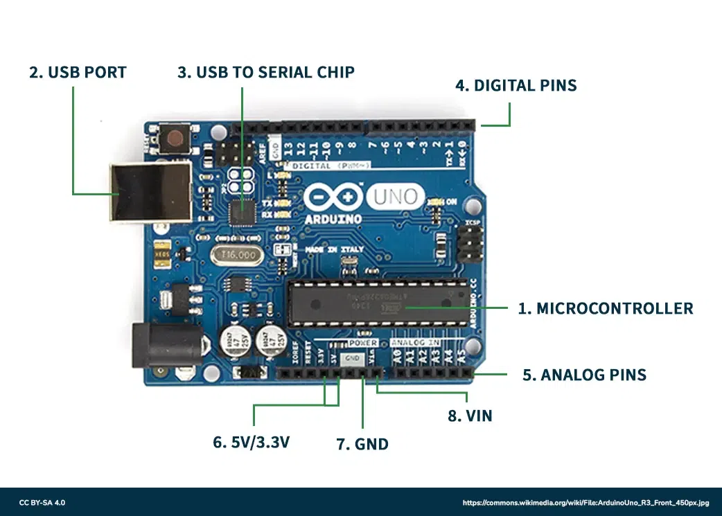
- Microcontroller — controls program execution and runs the logic you write
- USB port — connects the board to your computer
- USB-to-serial chip — handles uploading your code from the computer to the microcontroller
- Digital pins — control things like LEDs using simple binary logic, 0 or 1
- Analog pins — accept analog input, values that aren't just on or off
- 5V / 3.3V pins — supply power to external components
- GND — the ground reference every circuit needs
How It Runs
An Arduino program works in a loop: configure a sensor to read input, decide what to do with that reading, act on it — for example turning on a light — and repeat. Depending on how much delay you write into the code, each pass through that loop can take anywhere from microseconds up.
Circuit Basics
The simplest possible Arduino circuit is an LED wired through a resistor to a digital pin and ground.
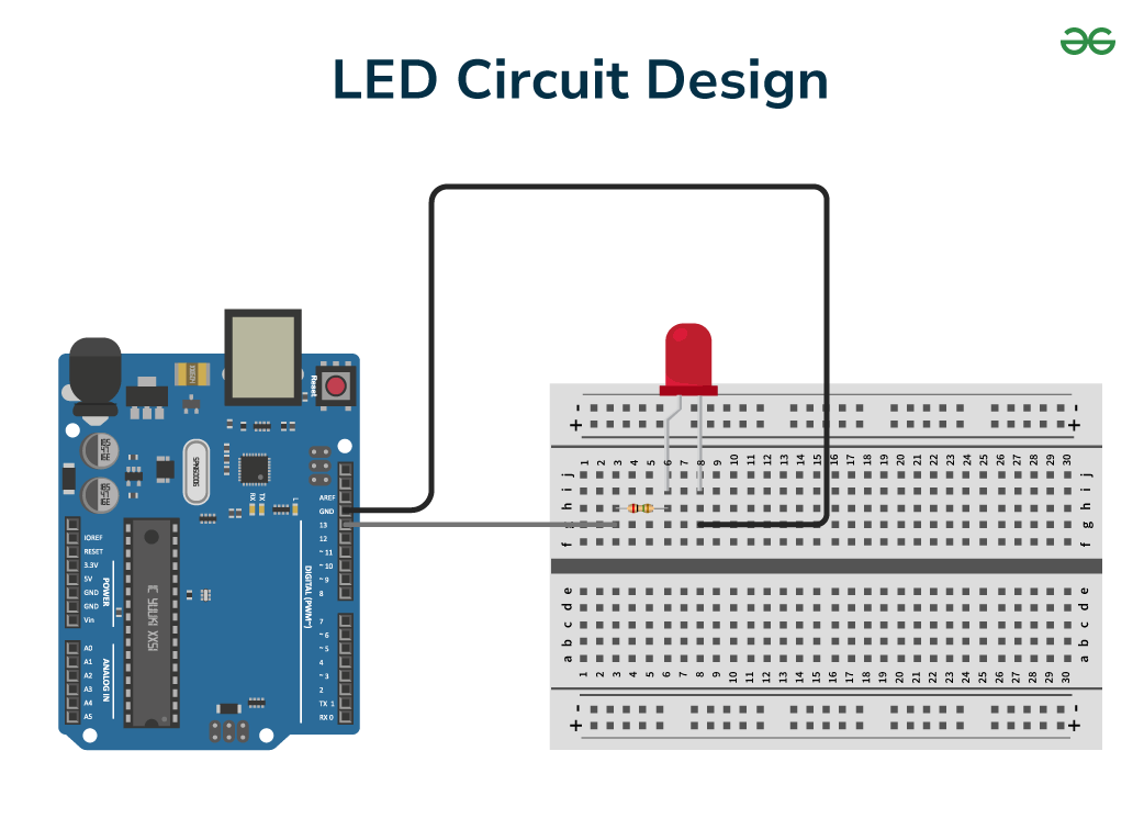
The resistor limits how much current flows through the LED, protecting it from burning out. When your code sets the pin HIGH, current flows through the circuit exactly as programmed and the LED lights up. Set it LOW, and no current flows — the LED stays off.
Analog vs Digital Signals
Everything an Arduino reads or writes falls into one of two categories.
Digital Signals
A digital pin only ever reports one of two states: HIGH (5V) or LOW (0V) — a switch, nothing between. That's enough to send commands and move data as sequences of on/off pulses.
Analog Signals
Real-world quantities rarely land neatly on "on" or "off," so the analog pins measure anything between 0V and 5V instead. analogRead() uses a 10-bit ADC and reports a number from 0 to 1023. Going the other direction, analogWrite() (PWM) only takes 8-bit values, 0 to 255 — reading and writing use different resolutions, which trips up a lot of beginners.
Don't assume the number you read matches the number you'd write back. A potentiometer read with analogRead() gives 0–1023; to use that value for LED brightness with analogWrite() you need to rescale it to 0–255 first, typically with map().
Sensors and Actuators
Most Arduino projects boil down to two kinds of components talking to your code.
Sensors
A sensor turns something physical — heat, light, distance, sound — into an electrical signal Arduino can measure. On the code side that usually collapses into one call:
sensorValue = sensor.read();
Actuators
An actuator does the opposite — it changes a physical state based on what your code decides, whether that's lighting an LED or spinning a motor.
digitalWrite(LED, HIGH);   // turn on an LED
digitalWrite(LED, LOW);    // turn off an LED
analogWrite(motor, 255);   // set a motor to receive 255 bits
Sketch Structure & Core Functions
A full Arduino project is called a sketch, saved with a .ino extension. Every sketch is built from a small set of functions.
void setup() {
  // configure the program: pin modes, libraries, serial, etc.
}
void loop() {
  // the main program — runs continuously while the board is on
}
void loop() {
  digitalWrite(LED, HIGH); // turn on an LED
  delay(1000);             // paused for 1 second (1000 milliseconds)
  digitalWrite(LED, LOW);  // the LED is turned off
}
While delay() is waiting, your Arduino can't do anything else — no reading sensors, no responding to buttons. For anything that needs to happen on its own schedule alongside other code, reach for millis() instead.
unsigned long firstEventTime = 0;
unsigned long secondEventTime = 0;
const long firstEventInterval = 5000;
const long secondEventInterval = 1000;

void setup() {
  // any necessary setup can be done here
}

void loop() {
  unsigned long currentTime = millis();

  if (currentTime - firstEventTime >= firstEventInterval) {
    firstEventTime = millis();
    // execute code for the first event every 5 seconds
  }

  if (currentTime - secondEventTime >= secondEventInterval) {
    secondEventTime = millis();
    // execute code for the second event every 1 second
  }
}
Libraries
Libraries package up common hardware and software tasks — reading a sensor type, driving a motor driver, talking to a display — so you don't have to write that logic from scratch. Pull one in with:
#include <Library.h>
A Complete Example Sketch
This sketch reads an analog sensor and switches an LED on when the reading drops below a threshold — the same pattern behind a huge share of beginner Arduino projects.
int sensorPin = A1; // analog pin at A1
int ledPin = 5;     // digital pin at pin 5
int sensorValue;

// configure the sketch
void setup() {
  Serial.begin(9600);      // initialize serial communication
  pinMode(ledPin, OUTPUT); // define output pin
}

void loop() {
  sensorValue = analogRead(sensorPin);
  Serial.print("Sensor value is: "); // print a message
  Serial.println(sensorValue);       // print the value to the serial monitor

  // conditional statement
  if (sensorValue < 100) {
    digitalWrite(ledPin, HIGH); // turn on the LED on pin 5
  } else {
    digitalWrite(ledPin, LOW);
  }
}
Swap the sensor for a potentiometer and change the threshold from 100 to a few different values while watching the Serial Monitor. Once you can predict exactly when the LED will switch, you understand analog thresholds.
Why Choose Arduino?
- Beginner-friendly — one of the best ways to start programming in electronics
- No prerequisites — no prior electronics experience required
- Flexible — works standalone or paired with other devices like Raspberry Pi
- Open-source — huge community, accessible on every major platform
- Wide variety — many board designs for different power, size and I/O needs
That combination shows up everywhere — controlling 3D printers, powering maker projects, teaching programmable electronics in college labs, driving robots that sense and respond to their environment, and collecting sensor data for IoT systems.
Installing the Arduino IDE
The IDE is the software on your computer where you write and upload sketches. It's free and available for Windows, Mac and Linux.
Windows
- Plug the board into your computer
- Open Control Panel → System and Security → System → Device Manager
- Find the Arduino UNO listed under Ports (as COMxx)
- Right-click it and choose "Update Driver Software"
- Browse to the
ArduinoUNO.inffile in the Drivers folder of your Arduino install
Mac OS
- Extract the downloaded .zip file
- Open the extracted Arduino application
- No additional drivers are needed
Ubuntu / Linux
- Download the Linux AppImage for Arduino IDE 2.x from arduino.cc/en/software
- Make it executable and run it — no separate Java install needed for the 2.x IDE
chmod +x arduino-ide_2.x.x_Linux_64bit.AppImage
./arduino-ide_2.x.x_Linux_64bit.AppImage
Your user account usually needs to be in the dialout group to access the serial port. Run sudo usermod -aG dialout $USER, then log out and back in.
Test It With Blink
- Connect the Arduino board to your computer
- Open the Arduino IDE
- Go to File → Examples → Basics → Blink
- Select Tools → Board → Arduino Uno
- Select Tools → Serial Port → the COM port on Windows, or
/dev/tty.usbmodemon Mac/Linux - Click Upload
- Watch the RX/TX LEDs flicker, then wait for "Done uploading"
If the built-in LED starts blinking once a second, your board, cable, drivers and IDE are all confirmed working — and you're ready to build something that actually does something.